The mechanics' magazine, museum, register, journal, and gazette. No. 1128, Saturday, March 22, 1845 / edited by J.C. Robertson.
- Date:
- [1845]
Licence: Public Domain Mark
Credit: The mechanics' magazine, museum, register, journal, and gazette. No. 1128, Saturday, March 22, 1845 / edited by J.C. Robertson. Source: Wellcome Collection.
5/20 (page 195)
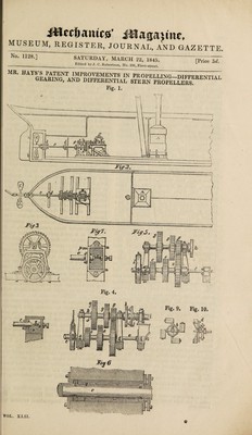
![tion, taken through a vessel fitted with his improved auxiliary steam power. Fig. 2 is a plan of the same. A A is the boiler and furnace, and B B one of Beale’s patent improved ro¬ tary engines, (any other engine or motive power may be employed, this engine being merely selected for the purpose of illustrating the invention,) C is an ordi¬ nary propeller with any number of blades which may be considered most advisable. c c is the propeller shaft, on the inner end of which is the differential gearing e e e, shown on an enlarged scale in figures 3, 4, and 5. Another shaft, f f, furnished with a feather, h h, is mounted in bear¬ ings immediately above the inner end of the propeller shaft, and also carries toothed wheels, g g g, of different dia¬ meters, which w'heels are mounted on and made to slide easily along the shaft f f. When it is required to change the speed of the propeller, the feather A, of the shaft f passes through and looses all the wheels, g g g, and of course carries them round with it. The shaft of the engine is seen at i, and carries at its end a clutch, /, which, when brought into contact with the clutch box k, on the inner end of the shaft f causes the latter with its wheels, g g g, to be carried round and drive the propeller shaft. . It will be observed, by referring to the figures, that the slowest motion is repre¬ sented as in gear, as would be the case in calms or very light winds, when the whole power of the engine only, rather than the speed of the propeller is re¬ quired. If a breeze were to spring up, then it would be necessary to increase the speed of the propeller. To effect this the engine must be temporarily detached by loosing the clutch: the second pair of wheels must then be put in gear, and the first put out of gear; then, upon con¬ necting the engine again, the speed of the propeller wilt be very much increased. If the breeze should freshen still more, the engine must be again detached, and the third pair of wheels put in gear, the others being previously put out of gear; as the wheels, g g g, all slide freely along the shaft this object is easily effect¬ ed by the attendant engineer. A friction brake l, of the ordinary kind, is mounted on the propeller shaft for the purpose of preventing it from revolving, while the toothed wheels are being put in and out of gear. 2. The reduction of friction is effected chiefly by means of a number of anti¬ friction rollers, q q q, which are placed round the shaft in the manner shown in the longitudinal view, fig. 6. These rollers are all placed round the shaft, and are allowed to revolve both on their own axes, and also round the shaft itself. The bearings are provided with proper packings, as at m m, to prevent the water from entering the vessel. At n n, figs. 4 and 5, there is also a bearing for re¬ sisting the horizontal thrust of the pro¬ peller shaft when in rapid rotation, which would otherwise quickly wear away the bearings in which the shaft is mounted. This bearing, n, is shown de¬ tached, and upon an enlarged scale, at figs. 7 and 8 ; fig. 7 is a view looking from above, and fig. 8 a transverse ver¬ tical section. The bearing consists of a metal box, which] is firmly screwed to a stationary framing in a convenient man¬ ner ; a pin, o, is screwed through one side of the bearing, and bears against one end of the shaft c c, as seen in the figures, and can be tightened up as circumstances may require by merely turning the screw head, whereby the shaft is prevented from wearing away the sides of the other bearings. The metal box n is supplied with water until about one-half of the end of the shaft c is immersed, as shown in the figure, and then a quantity of oil is poured in* which being the lighter fluid, always floats at the top ; a cock, p, is placed on one side of the box, exactly opposite to the centre of the shaft, for the purpose of ascertaining the exact level of the two liquids. By constructing the bearing in this manner, and keeping it properly supplied with water and oil, it is kept perfectly cool, as the water in the box abstracts the heat from the work¬ ing parts, and prevent them from getting overheated. 3. The “ novel construction of pro¬ pellers” is represented in figs. 9 and 10. It consists in mounting any convenient number of perfectly straight blades at an angle round the shaft, in such a manner that the said angle may be varied accord¬ ing to the speed at which the vessel is required to progress. The angle of the blades is regulated by a ring, 6, which must be firmly connected either to the propeller shaft or to radial arms which carry the propellers.. In the figures, the ring b is firmly affixed to the propeller o 2](https://iiif.wellcomecollection.org/image/b30390783_0005.jp2/full/800%2C/0/default.jpg)